
Page 28 - 3D Metal Printing Fall 2018
P. 28
3D CT Scanning for AM Inspection
helps improve productivity by eliminating issues that potentially cause post-pro- duction problems.
CT Versus Other NDT Techniques
Popular nondestructive-testing (NDT) techniques used in AM include metrology, ultrasound and x-ray. How do they meas- ure up?
Metrology, the study of measurement and a basic requirement in any field of science and technology, is expected to enforce, validate and verify predefined standards for traceability, accuracy, reli- ability and precision. All of these factors affect measurement validity. Without destructive testing, full metrology has been performed only on components’ exterior dimensions. A highly detailed component would be inspected using a time-consuming coordinate-measuring machine, touch-probe process or vision system to map exterior surfaces. Past internal-inspection methods required a 2D X-ray of the component or NDT.
The latest CT-scanning systems com- bine CT scanning with metrology meas- urements in a single scan, as part of a single simple step, an important development for AM companies.
Ultrasound imaging, also called ultra- sound scanning or sonography, employs a small transducer (probe) and ultrasound gel placed directly on the object to be imaged. High-frequency sound waves transmit from the probe through the gel and into the object. The ultrasound process produces an electromagnetic field, with the induced field in the part measured. A discontinuity shows up as a blip on the screen, allowing users to find tight cracks on a surface that may be dif- ficult to impossible to see.
Though popular in manufacturing, ultrasonic testing, requiring a small trans- ducer and a control unit to emit the signal, then coupling it directly to the part, can be a messy and complicated process.
X-rays, a form of electromagnetic radi- ation, allow users to peer inside of a part for detailed inspections. Emitted radiation can make such an inspection, already a slow process, a safety hazard.
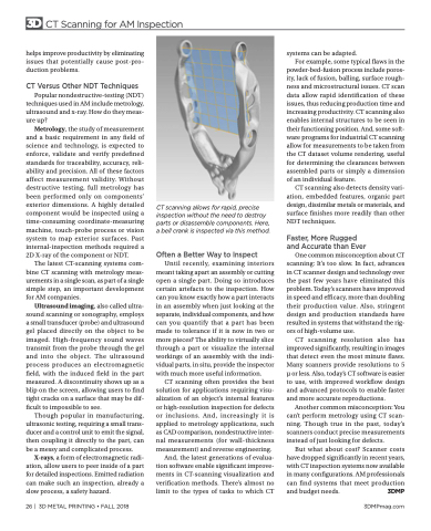
CT scanning allows for rapid, precise inspection without the need to destroy parts or disassemble components. Here, a bell crank is inspected via this method.
Often a Better Way to Inspect
Until recently, examining interiors meant taking apart an assembly or cutting open a single part. Doing so introduces certain artefacts to the inspection. How can you know exactly how a part interacts in an assembly when just looking at the separate, individual components, and how can you quantify that a part has been made to tolerance if it is now in two or more pieces? The ability to virtually slice through a part or visualize the internal workings of an assembly with the indi- vidual parts, in situ, provide the inspector with much more useful information.
CT scanning often provides the best solution for applications requiring visu- alization of an object’s internal features or high-resolution inspection for defects or inclusions. And, increasingly it is applied to metrology applications, such as CAD comparison, nondestructive inter- nal measurements (for wall-thickness measurement) and reverse engineering.
And, the latest generations of evalua- tion software enable significant improve- ments in CT-scanning visualization and verification methods. There’s almost no limit to the types of tasks to which CT
systems can be adapted.
For example, some typical flaws in the
powder-bed-fusion process include poros- ity, lack of fusion, balling, surface rough- ness and microstructural issues. CT scan data allow rapid identification of these issues, thus reducing production time and increasing productivity. CT scanning also enables internal structures to be seen in their functioning position. And, some soft- ware programs for industrial CT scanning allow for measurements to be taken from the CT dataset volume rendering, useful for determining the clearances between assembled parts or simply a dimension of an individual feature.
CT scanning also detects density vari- ation, embedded features, organic part design, dissimilar metals or materials, and surface finishes more readily than other NDT techniques.
Faster, More Rugged and Accurate than Ever
One common misconception about CT scanning: It’s too slow. In fact, advances in CT scanner design and technology over the past few years have eliminated this problem. Today’s scanners have improved in speed and efficacy, more than doubling their production value. Also, stringent design and production standards have resulted in systems that withstand the rig- ors of high-volume use.
CT scanning resolution also has improved significantly, resulting in images that detect even the most minute flaws. Many scanners provide resolutions to 5 μ or less. Also, today’s CT software is easier to use, with improved workflow design and advanced protocols to enable faster and more accurate reproductions.
Another common misconception: You can’t perform metrology using CT scan- ning. Though true in the past, today’s scanners conduct precise measurements instead of just looking for defects.
But what about cost? Scanner costs have dropped significantly in recent years, with CT inspection systems now available in many configurations. AM professionals can find systems that meet production and budget needs. 3DMP
26 | 3D METAL PRINTING • FALL 2018
3DMPmag.com
