
Page 35 - 3D Metal Printing Spring 2017
P. 35
3D
reverse-engineer and print an entire exhaust stack for a WWII P-51 Mustang long-range, single-seat fighter. Working with Rob Connelly, former Proto Labs vice president of AM and owner of one of the 150 or so surviving P-51 planes, nicknamed Hurry Home Honey, Murray and Chu looked for the per- fect example of a part they could reverse-engineer and print to demonstrate the value of AM.
“A lot of the replacement parts for these planes
are in short supply and are very expensive,” Murray
tells 3D Metal Printing. “There just aren’t many of
these planes or spare parts around. To display the role that metal AM can play in terms of aircraft operational readiness, we looked for a part on Rob’s plane that was visible, showed a lot of wear and tear, but was not necessarily flight-critical, and settled on the exhaust manifold of the plane’s Merlin V12 1500-hp engine.”
The original manifold was manufactured from four parts—a cast base, two stamped clamshell pieces welded together, and a cast ring. There’s a total of 34 in. of weld seam, and some of those welds exhibited quite a bit of rework, done to repair damage resulting from excessive high-temperature cycling in service.
Scanning to Create the Data Cloud
Late in 2016, Chu’s team at PADT blue-light scanned and dig- itized one of the plane’s exhaust stacks, using a Zeiss Comet 6 high-resolution scanner. “We captured some 2 million data- points,” Chu says, “scanning at a resolution of 0.0005 in., and then cleaned the data to create the surface mesh. That mesh then was used as the basis to define geometric features and dimensions to create a 3D CAD model, eventually converted into an STL file for 3D printing.”
Chu and his team also performed some simulation work on the CAD model, using Ansys simulation software to study how the resulting 3D-printed exhaust stack would perform in service. They ran heat-transfer and fluid-flow analyses, “the idea being that we could, if we wanted to, modernize and optimize the design of a part to improve its performance over an original design,” Chu says.
Chu then sent two STL files to Concept Laser for printing—
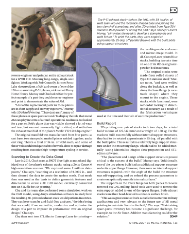
The P-51 exhaust stack—before (far left), with 34 total in. of weld seam around the racetrack-shaped base and joining the two clamshell stampings; and after, 3D-printed from Type 304 stainless-steel powder. “Printing the part,” says Concept Laser’s Murray, “eliminates the need to develop a stamping die and weld fixture.” To print the parts, they were angled at approximately 25 deg. off parallel (below) with the build plate using support structures.
the resulting model and a sec- ond mirror-image model. In all, Concept Laser printed four stacks, building two at a time on one of its M2 casing laser- powder-bed machines.
“The original stacks were made from rolled sheets of Type 316 stainless steel,” Mur- ray notes, “and were welded along the backside, as well as along the base flange (a race- track shape) where they mount to the engine. These stacks, while functional, were somewhat lacking in dimen- sional accuracy, as a result of the fabrication techniques
used at the time and the rush of wartime production.”
Build Report
3D-printing one pair of stacks took two days, for a total build volume of 125,542 mm3 and a weight of 1.98 kg. For the stacks to build successfully without internal support structures, they had to be rotated approximately 25 deg. off parallel with the build plate. This resulted in a relatively large support struc- ture under the mounting flange, which had to be added man- ually (using Materialise Magics data-preparation and STL- editor software).
“The placement and design of the support structure proved critical to the success of the build,” Murray says. “Additionally, one of the two pieces built had an additional support structure under its upper flange. However, there were no internal support structures required—with the angle of the build the structure was self-supporting, and we refined the process parameters to create exceptionally smooth internal surfaces.”
The supports on the lower flange for both pieces then were removed via CNC milling; hand tools were used to remove the extra support added to one of the upper flanges. Both exhaust stacks were then bead-blasted to enhance surface finish.
“This was a great exercise that’s suitable for numerous military applications and very relevant to the future use of 3D metal printing to maintain fleets in the field,” Chu says. “Maintaining spare-parts inventory has become a significant challenge, for example, to the Air Force. Additive manufacturing could be the solution.” 3DMP
3DMPmag.com
SPRING 2017 • 3D METAL PRINTING | 33
