
Page 19 - 3D Metal Printing Spring 2017
P. 19
3D
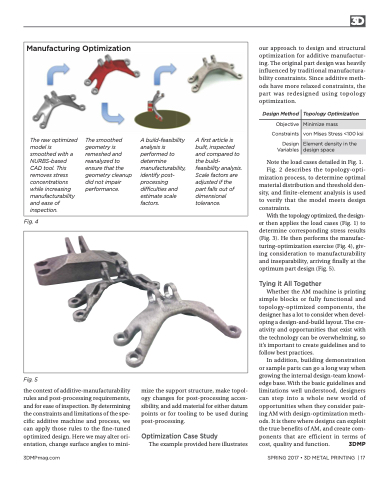
Manufacturing Optimization
The raw optimized model is smoothed with a NURBS-based CAD tool. This removes stress concentrations while increasing manufacturability and ease of inspection.
The smoothed geometry is remeshed and reanalyzed to ensure that the geometry cleanup did not impair performance.
A build-feasibility analysis is performed to determine manufacturability, identify post- processing difficulties and estimate scale factors.
A first article is built, inspected and compared to the build- feasibility analysis. Scale factors are adjusted if the part falls out of dimensional tolerance.
Design Method
Topology Optimization
Objective Constraints
Design Variables
Minimize mass
von Mises Stress <100 ksi
Element density in the design space
Fig. 4
our approach to design and structural optimization for additive manufactur- ing. The original part design was heavily influenced by traditional manufactura- bility constraints. Since additive meth- ods have more relaxed constraints, the part was redesigned using topology optimization.
Note the load cases detailed in Fig. 1.
Fig. 2 describes the topology-opti- mization process, to determine optimal material distribution and threshold den- sity, and finite-element analysis is used to verify that the model meets design constraints.
With the topology optimized, the design- er then applies the load cases (Fig. 1) to determine corresponding stress results (Fig. 3). He then performs the manufac- turing-optimization exercise (Fig. 4), giv- ing consideration to manufacturability and inseparability, arriving finally at the optimum part design (Fig. 5).
Tying it All Together
Whether the AM machine is printing simple blocks or fully functional and topology-optimized components, the designer has a lot to consider when devel- oping a design-and-build layout. The cre- ativity and opportunities that exist with the technology can be overwhelming, so it’s important to create guidelines and to follow best practices.
In addition, building demonstration or sample parts can go a long way when growing the internal design-team knowl- edge base. With the basic guidelines and limitations well understood, designers can step into a whole new world of opportunities when they consider pair- ing AM with design-optimization meth- ods. It is there where designs can exploit the true benefits of AM, and create com- ponents that are efficient in terms of cost, quality and function. 3DMP
Fig. 5
the context of additive-manufacturability rules and post-processing requirements, and for ease of inspection. By determining the constraints and limitations of the spe- cific additive machine and process, we can apply those rules to the fine-tuned optimized design. Here we may alter ori- entation, change surface angles to mini-
mize the support structure, make topol- ogy changes for post-processing acces- sibility, and add material for either datum points or for tooling to be used during post-processing.
Optimization Case Study
The example provided here illustrates
3DMPmag.com
SPRING 2017 • 3D METAL PRINTING | 17
