
Page 16 - 3D Metal Printing Spring 2017
P. 16
3D FEATURE
Designing for Additive
Manufacturing, Part III: Leveraging Optimization Methods
There is much more to optimizing geometry beyond using the straight output from a design tool. The most efficient AM structures only result when combining optimization methods with real-world AM expertise. BY CAITLIN OSWALD AND JOE MANZO
In Part I of this article (AM Design: Con- siderations for the Full Value Stream, spring 2016 issue of 3D Metal Printing), the discussion focused on integrating the entire manufacturing process into the design thought process. Part II (winter 2017 issue) covered manufacturability considerations. Here we discuss oppor- tunities afforded by linking AM to design-
Caitlin Oswald is an additive-manufac- turing specialist with LAI International, Inc., Scottsdale, AZ; 612/300-8722, www.laico.com. Joe Manzo is CEO of Titan Industries, Tempe, AZ; 480/652-3996, www.titan.industries.
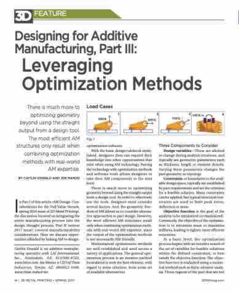
Load Cases
Fig. 1
optimization software.
With the basic design rulebook estab-
lished, designers then can expand their knowledge into other opportunities that exist when using AM technology. Pairing the technology with optimization methods and software tools allows designers to take their AM components to the next level.
There is much more to optimizing geometry beyond using the straight output from a design tool. In order to effectively use the tools, designers must consider several factors. And, the geometric free- dom of AM allows us to consider alterna- tive approaches to part design. However, the most efficient AM structures result only when combining optimization meth- ods with real-world AM expertise, since the output of the optimization methods is not necessarily AM-friendly.
Mathematical optimization methods are well-established and used across a variety of applications. The general opti- mization process is an iterative method formulated to seek the best element, with regard to some criterion, from some set of available alternatives.
Three Components to Consider
Design variables—These are allowed to change during analysis iterations, and typically are geometric parameters such as thickness, length or element density. Varying these parameters changes the part geometry or topology.
Constraints, or boundaries to the avail- able design space, typically are established by part requirements and set the criterion for a feasible solution. Many constraints can be applied, but typical structural con- straints are used to limit peak stress, deflection or mass.
Objective function is the goal of the analysis to be minimized (or maximized). Commonly, the objective of the optimiza- tion is to minimize mass or maximize stiffness, leading to lighter, more efficient structures.
At a basic level, the optimization process begins with an iterative search of the set of variables for feasible solutions within the defined constraints, to best satisfy the objective function. The objec- tive function is evaluated using a numer- ical method such as finite-element analy- sis. Those regions of the part that are not
8000 lb.
1
2
8500 lb.
3
5000 lb.-in.
4
9500 lb.
14 | 3D METAL PRINTING • SPRING 2017
3DMPmag.com
