
Page 28 - 3D Metal Printing Fall 2019
P. 28
3D Automated Calibration if one laser sees 100-percent utilization
and the other sees less, say 50 percent. Shops must therefore pay close attention to laser scheduling—this means knowing the path of the lasers. In addition, engi-
neers must examine how laser soot affects the scheduling, and how well the lasers coordinate their efforts when printing the contour and core of larger parts.
Several related issues arise when con-
sidering soot management, gas flow and laser scheduling. A quick way to derail a build: have one laser shoot through the soot cloud created by the other. Therefore, given the tight space in which the lasers operate, each laser’s path must be carefully planned. Shooting through the soot cloud reduces beam intensity when it hits the metal powder, which can lead to poor mechanical properties.
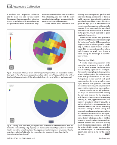
To ensure that neither laser gets in the other’s way, AM manufacturers can adopt the “swim lane” method. Here, each laser stays within one of two parallel tracks (Fig. 5), with all track switches synchro- nized. This programming method allows both lasers to run at all times during a build, taking full advantage of the two- laser system.
Dividing the Work
A crucial engineering question (with more than one answer) is how to subdi- vide the work between the lasers when each is building a portion of a solid part. Consider, for example, printing a cylinder, where one laser prints the entire contour while multiple lasers work on the core. Parts printed in this way will look good on the surface due to the seamless outer layer, however this approach can cause sub-contour porosity, with any structural issues hidden by the clean outer surface.
To make overlay issues highly obvious, AM shops can task each laser with printing the core and contour for the structure, with the two sides connected by a zig-zag line (Fig. 6). The jagged connection will improve structural integrity and, like a wall of offset bricks, the connection line moves with each layer, further improving structure strength. When using this approach, any laser misalignment, which will diminish the surface finish of the part, also will make any issues with overlay immediately obvious and not hidden beneath a smooth surface. Automated cal- ibration ensures that the laser overlay meets tolerance requirements and that the surface finish remains unchanged in the overlay region. It also ensures high quality, non-porous metal for the core of the part. 3DMP
Fig. 5—As illustrated here, a “swim lane” programming method can ensure that neither laser gets in the other’s way, as each laser stays within one of two parallel tracks, with all track switches synchronized. This allows both lasers to run at all times during a build.
Fig. 6—Tasking each laser with printing the core and contour for the structure, with the two sides connected by a zig-zag line, can make overlay issues highly obvious and not hidden beneath a smooth surface. The jagged connection improves structural integrity and, like a wall of offset bricks, the connection line moves with each layer, further improving structure strength.
26 | 3D METAL PRINTING • FALL 2019
3DMPmag.com
